
The studio
Designers and makers in one team
SPRING JADE brings frame designers, product developers and the workshop under one roof, so the person who drew your frame can walk over to the people making it.
How we work
Our team has spent years making eyewear for brands around the world. We started SPRING JADE for brands that want something nobody else has: their own designs, developed properly and made consistently.
Each project has one project manager from brief to delivery. You talk to them, they talk to the designers and the workshop, and everything is written down in your project page.

Designers at work
Hand sketches and technical drawings on the desk
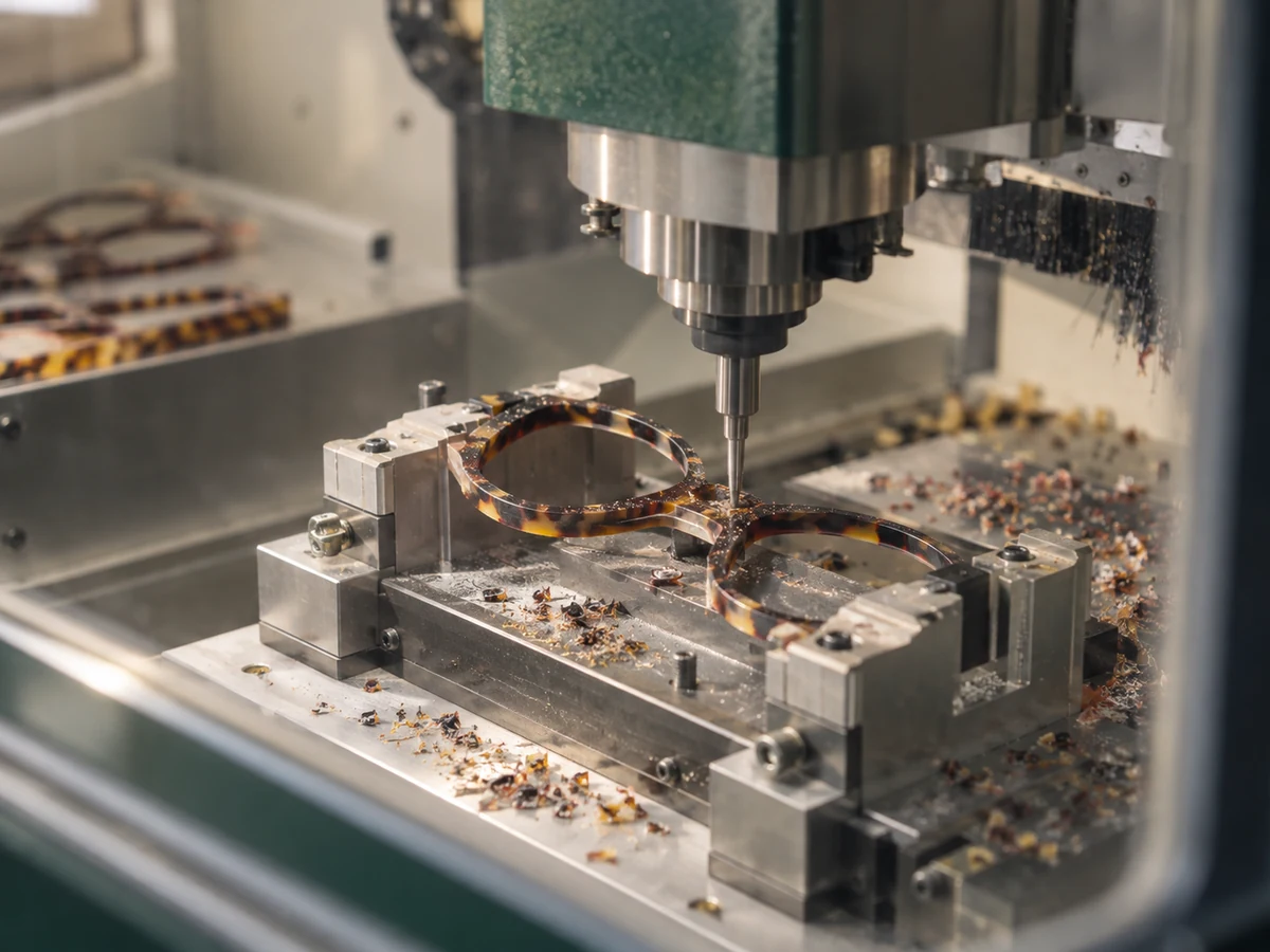
CNC milling
Acetate fronts being cut
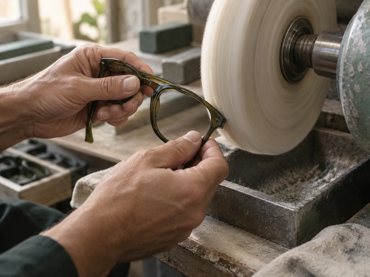
Hand polishing
Close-up of a frame on the polishing wheel
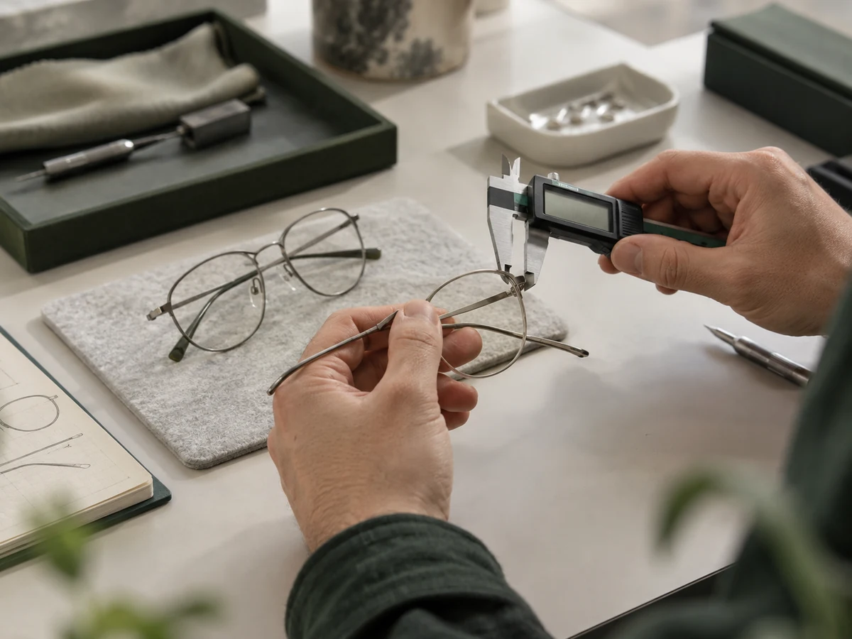
Quality control
Inspector measuring a frame against the approved sample
AI-generated illustrations shown temporarily. Studio photography will follow.
From material to frame
A different route for every material
Cutting a sheet, forming metal, moulding a resin and printing in powder are different crafts. Each starts with the construction of your approved design.
These are illustrative production routes. Specific operations depend on the material grade and frame construction. AI-generated process images will be replaced with workshop photography.
Production route 01
Cellulose acetate
Cut from sheet. Shaped and polished.
Colour and pattern begin in the sheet. Cutting and finishing bring out the depth of the material.
-

Step 01
Select & cut
Choose the sheet colour, thickness and pattern placement, then cut the front and temple blanks.
-
Step 02
Mill & shape
Machine the lens grooves, bridge and hinge pockets. Form the frame curvature and temple bends.
-
Step 03
Refine the surface
Smooth tool marks and edges, then polish or apply the approved matte finish.
-

Step 04
Assemble & check
Fit the hinges and approved lenses; check alignment, finish and fit against the sample.
What matters here
Pattern placement, consistent edge thickness and a smooth finish.
Production route 02
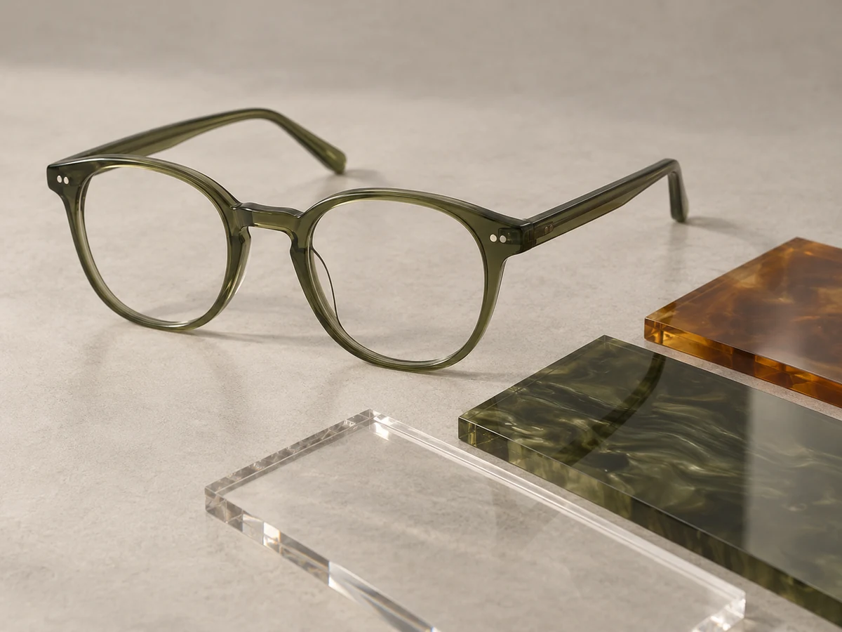
Bio-acetate
A sheet-based route, tuned to the material grade.
For sheet-based bio-acetate frames, the main operations resemble conventional acetate. Processing settings follow the selected supplier's guidance.
-
Step 01
Confirm the grade
Approve the supplier, sheet colour and thickness. Check the material documentation for any environmental claims.
-
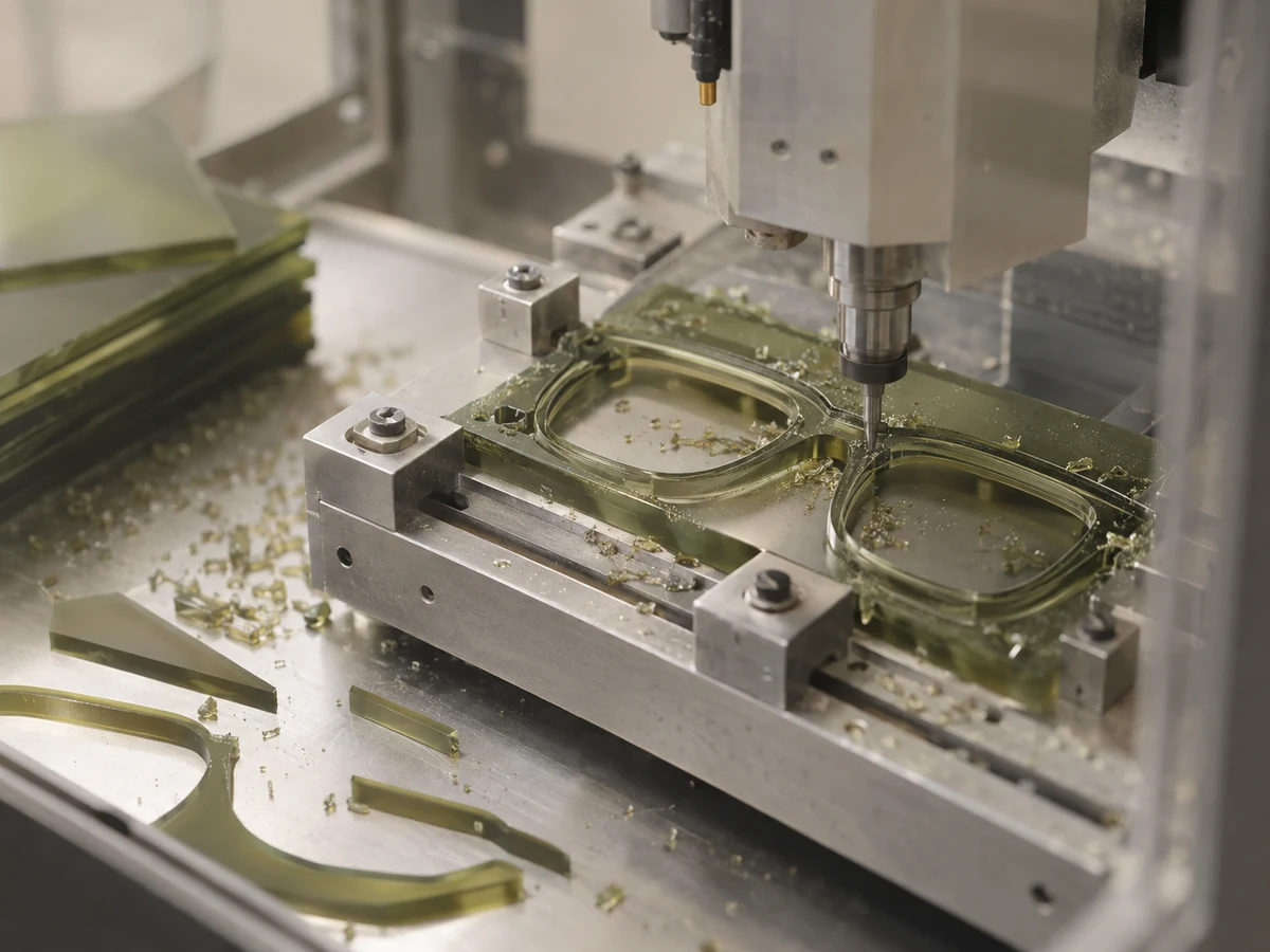
Step 02
Cut & machine
Cut the blanks and machine the frame contours, lens grooves and hinge seats.
-
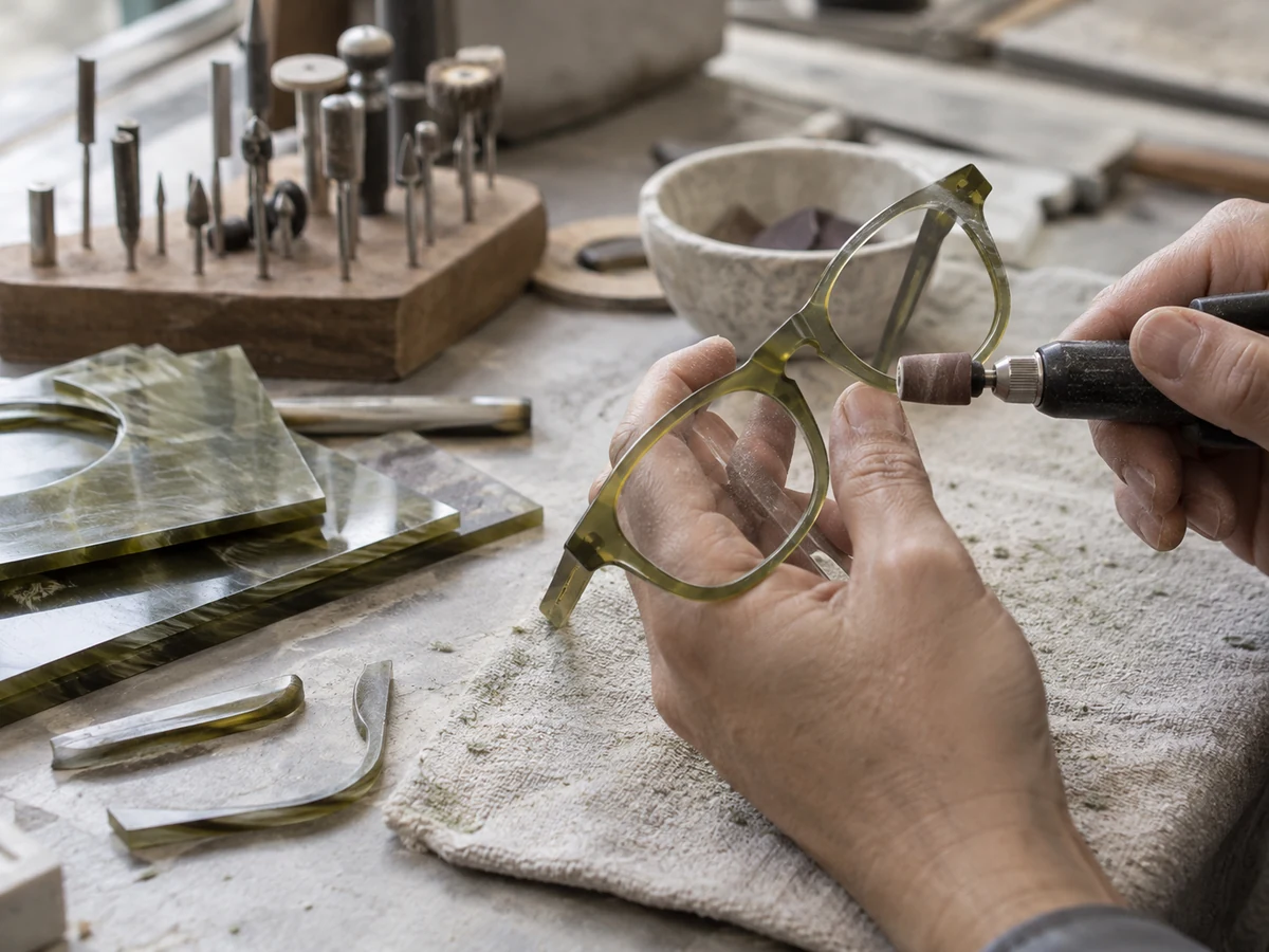
Step 03
Form & finish
Set the curvature and temple bends using settings suited to the grade, then smooth and finish the surface.
-
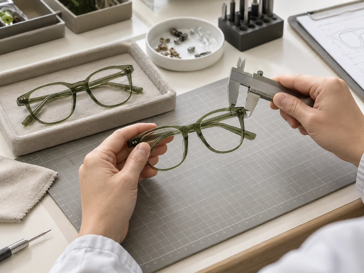
Step 04
Assemble & inspect
Install components and compare dimensions, colour and surface quality with the approved sample.
What matters here
Supplier-specific processing and evidence for material claims; appearance alone cannot identify bio-acetate.
Production route 03
Titanium and β-titanium
Precision parts. Controlled forming and joining.
The construction determines the route: sheet fronts, wire rims and flexible temples call for different tooling and assembly choices.
-

Step 01
Prepare the parts
Select the alloy and section. Cut, machine or form the front, bridge and temple components to suit the design.
-
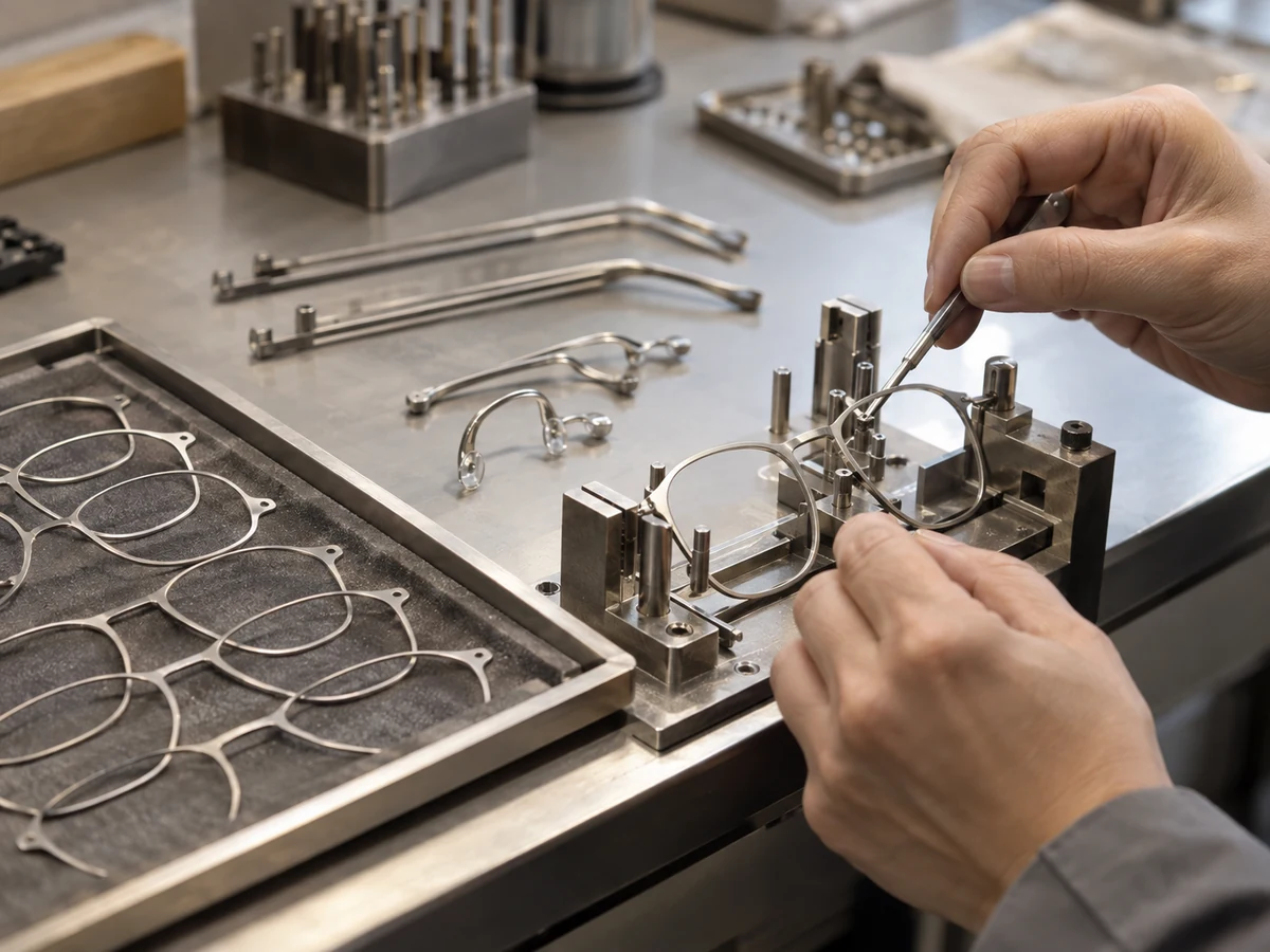
Step 02
Form & join
Shape the components in fixtures. Use the joining or mechanical assembly method specified for the construction.
-
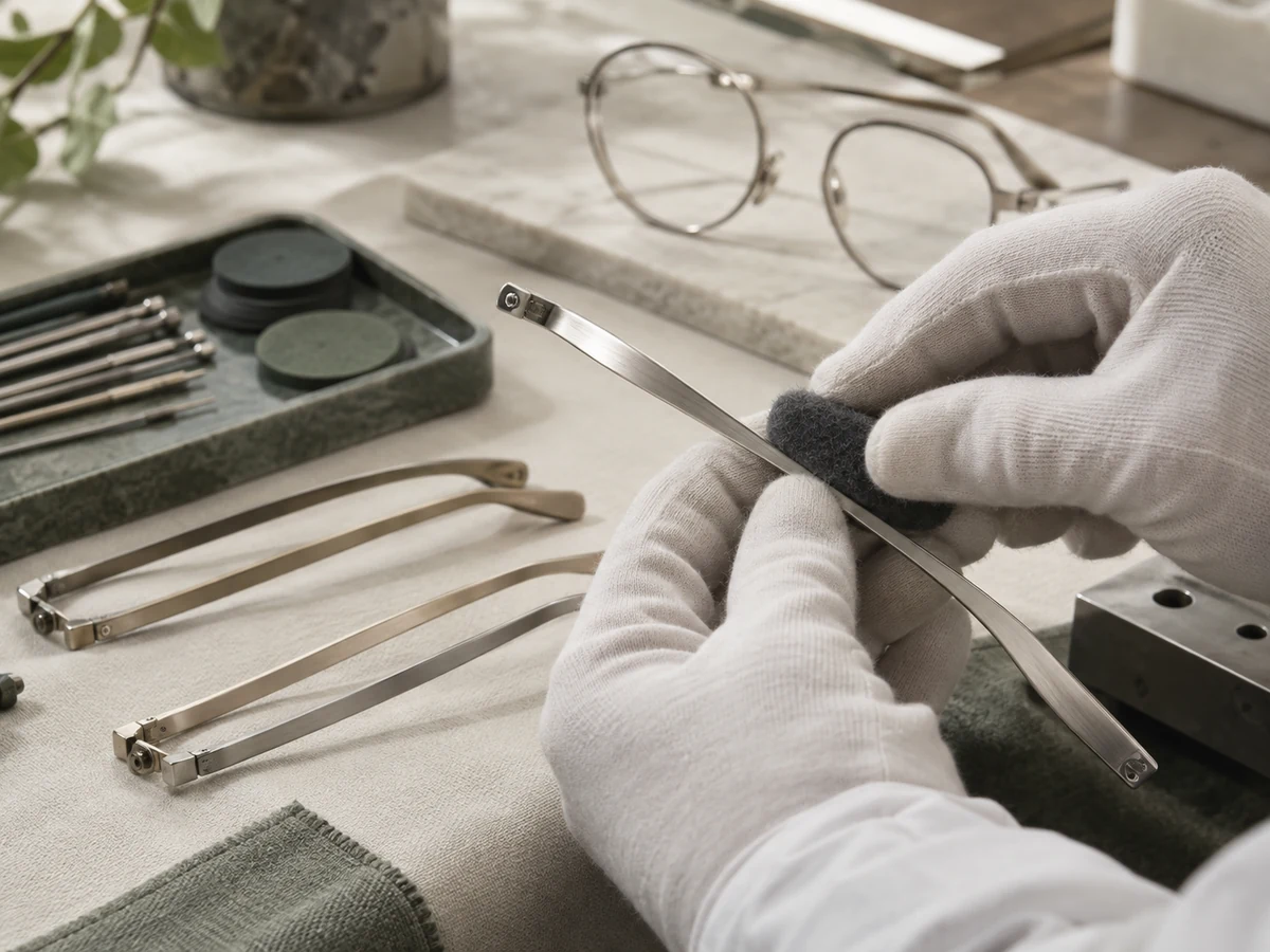
Step 03
Finish the metal
Clean and refine the surface, then apply the approved brushed, blasted or coated finish.
-
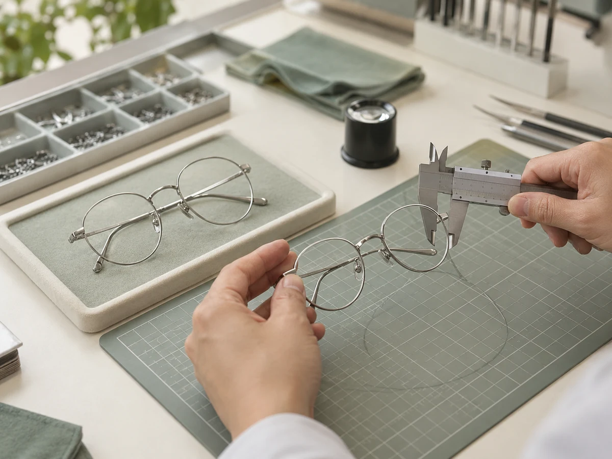
Step 04
Fit & verify
Assemble hinges, pads and tips. Check alignment, hinge action and the intended temple flexibility.
What matters here
Alloy selection, joint integrity and controlled spring behaviour in β-titanium components.
Production route 04
Stainless steel
Fine sheet or wire, formed into a frame.
Thin sheet constructions and wire-rim frames take different paths. The design defines how the parts are cut, formed and connected.
-

Step 01
Cut or form blanks
Prepare thin sheet components or wire rims to the approved frame outline.
-
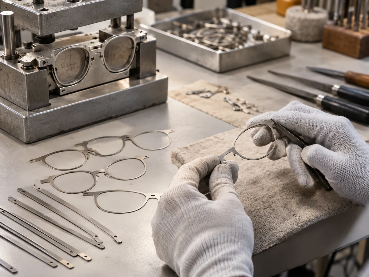
Step 02
Deburr & shape
Remove sharp edges and form the bridge, rims and temples using the appropriate fixtures.
-

Step 03
Connect & finish
Join or mechanically assemble the parts as designed, then brush, polish or coat the surface.
-
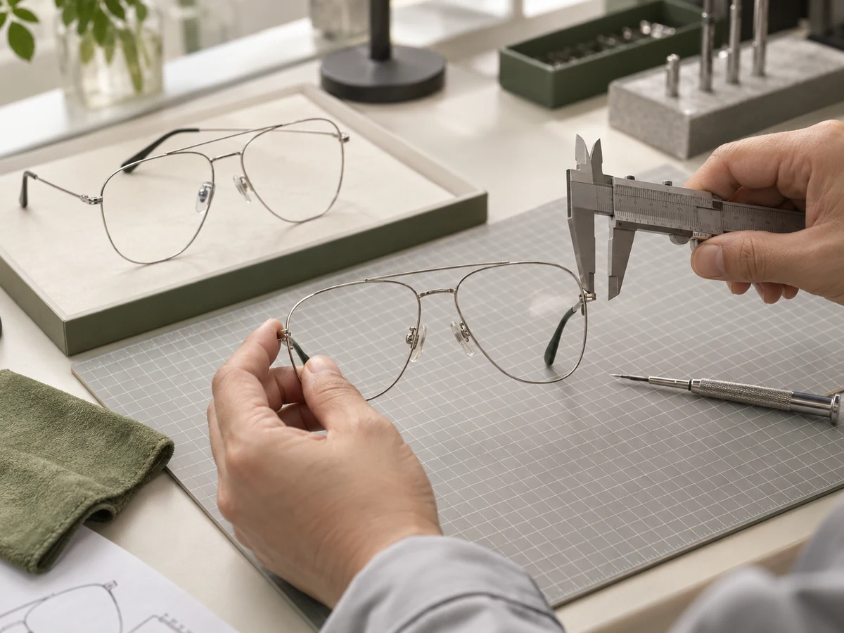
Step 04
Assemble & align
Fit pads and temple tips; check rim shape, hinge action, symmetry and lens seating.
What matters here
Clean edges, stable rim geometry and consistent surface finishing.
Production route 05
TR90 and Ultem
The tooling defines the shape.
Both follow an injection-moulding route, but they are different resin families. Drying and moulding settings must suit the exact grade.
-
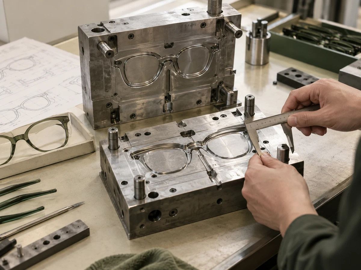
Step 01
Develop the mould
Translate the approved frame into tooling, accounting for gates, shrinkage and component fit.
-
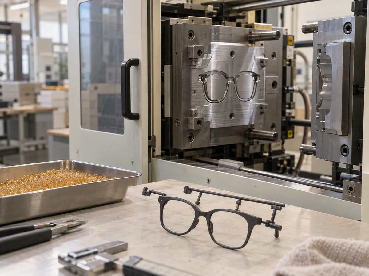
Step 02
Prepare & mould
Prepare the resin to its supplier specification, then inject it into the mould and cool before ejection.
-

Step 03
Trim & finish
Remove gates and flash. Apply approved colour or surface treatments where compatible with the material.
-

Step 04
Assemble & inspect
Install hardware and check dimensions, warpage, surface quality and fit.
What matters here
TR90 and Ultem are not interchangeable; process settings and finishing compatibility depend on the resin.
Production route 06
Wood
Work with the grain, from blank to finish.
Solid and laminated wood constructions need different blank preparation. Grain direction and stability guide the machining approach.
-
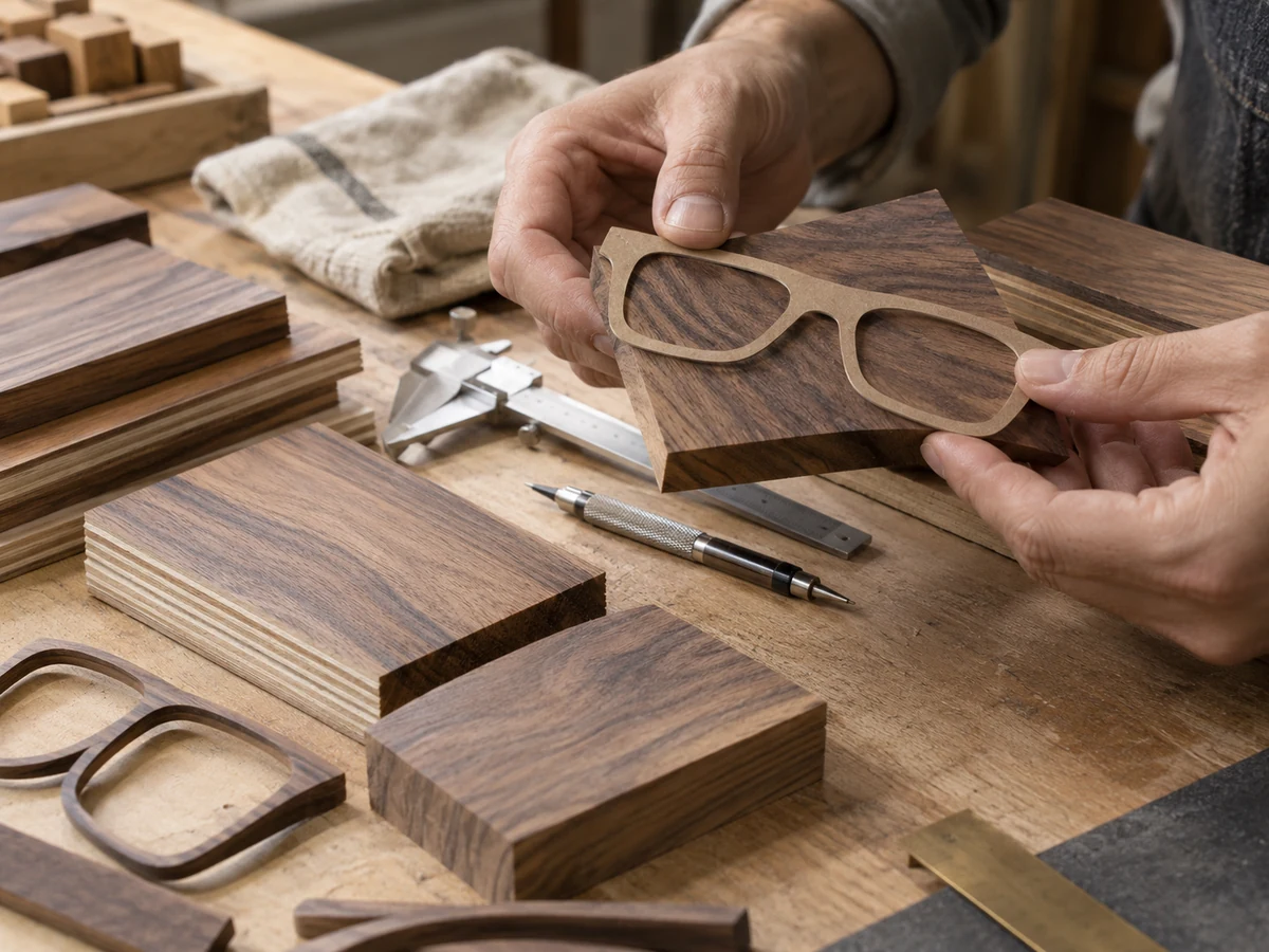
Step 01
Select the wood
Choose the species and grain, and prepare a suitable solid or laminated blank.
-
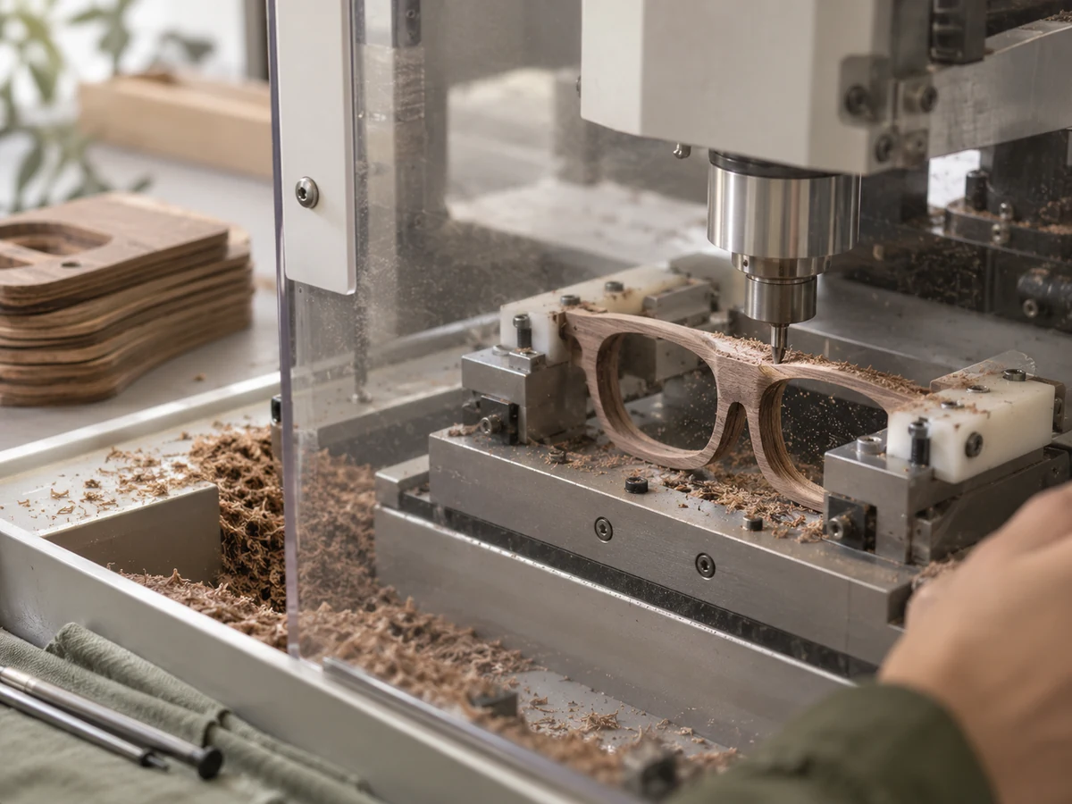
Step 02
Machine the frame
Cut the outline, lens grooves and hardware seats with allowances for the construction.
-

Step 03
Sand & protect
Smooth the contours and seal the surface with the approved oil or coating.
-

Step 04
Assemble & check
Fit the hinges and lenses, then check grain defects, component security and frame alignment.
What matters here
Grain direction, blank stability and careful lens-groove finishing.
Production route 07
Bamboo
A laminated construction, built layer by layer.
This example uses laminated bamboo. Strip preparation, bonding and layer orientation happen before the frame is machined.
-
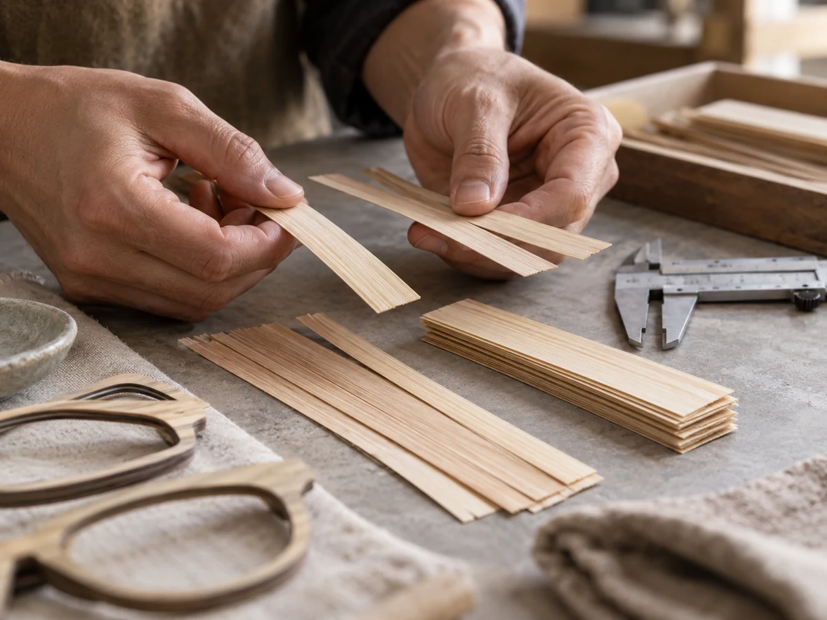
Step 01
Prepare the layers
Select and prepare bamboo strips or veneers for the approved laminated construction.
-
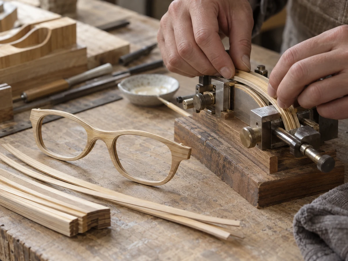
Step 02
Bond & press
Arrange and bond the layers, press the blank and allow the adhesive system to cure.
-
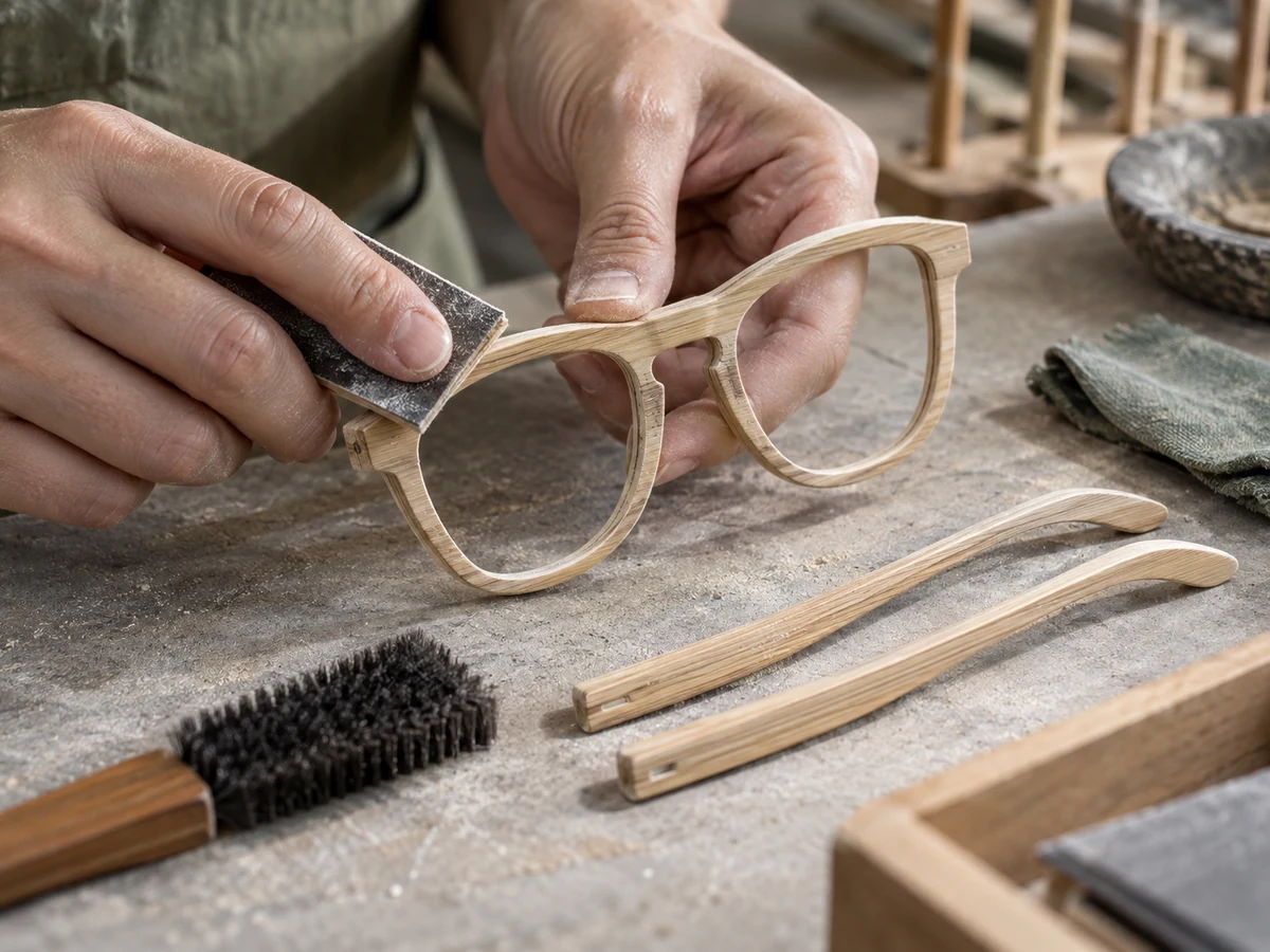
Step 03
Machine & finish
Machine the front and temples, smooth the edges and apply the chosen protective finish.
-

Step 04
Assemble & inspect
Fit components and check bond lines, edge quality, lens seating and alignment.
What matters here
Bond quality, layer orientation and protection of exposed edges.
Production route 08
Buffalo horn
Natural variation, finished with care.
Colour and grain vary from blank to blank. The chosen construction may use a single horn plate or laminated layers.
-
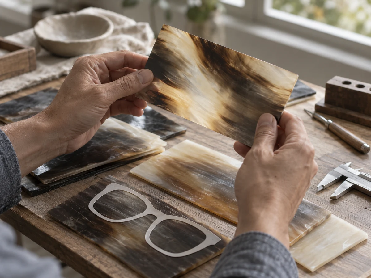
Step 01
Choose & prepare
Select suitable horn blanks for colour and grain; prepare the plate or laminated blank for the design.
-
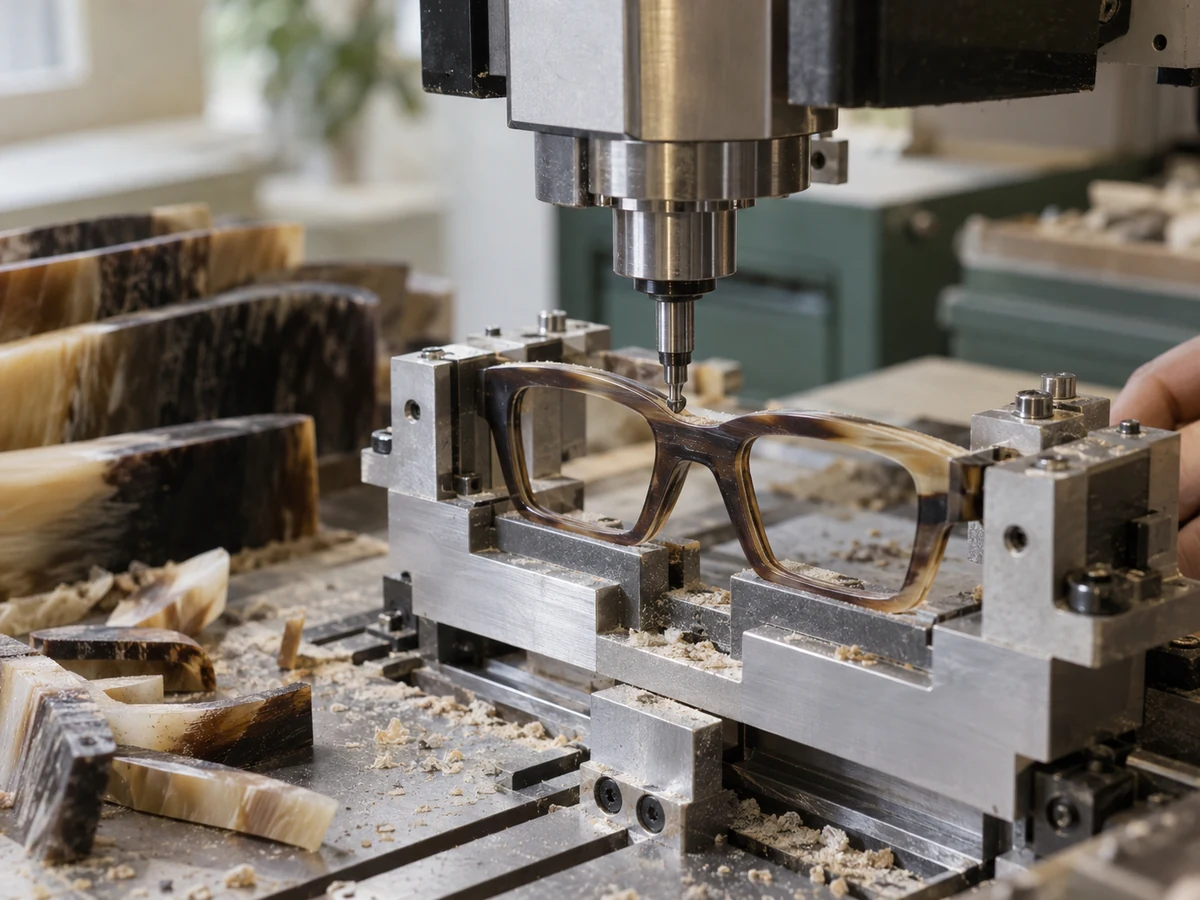
Step 02
Cut & refine
Cut the frame outline and machine the lens grooves and hinge seats while respecting the material's variation.
-
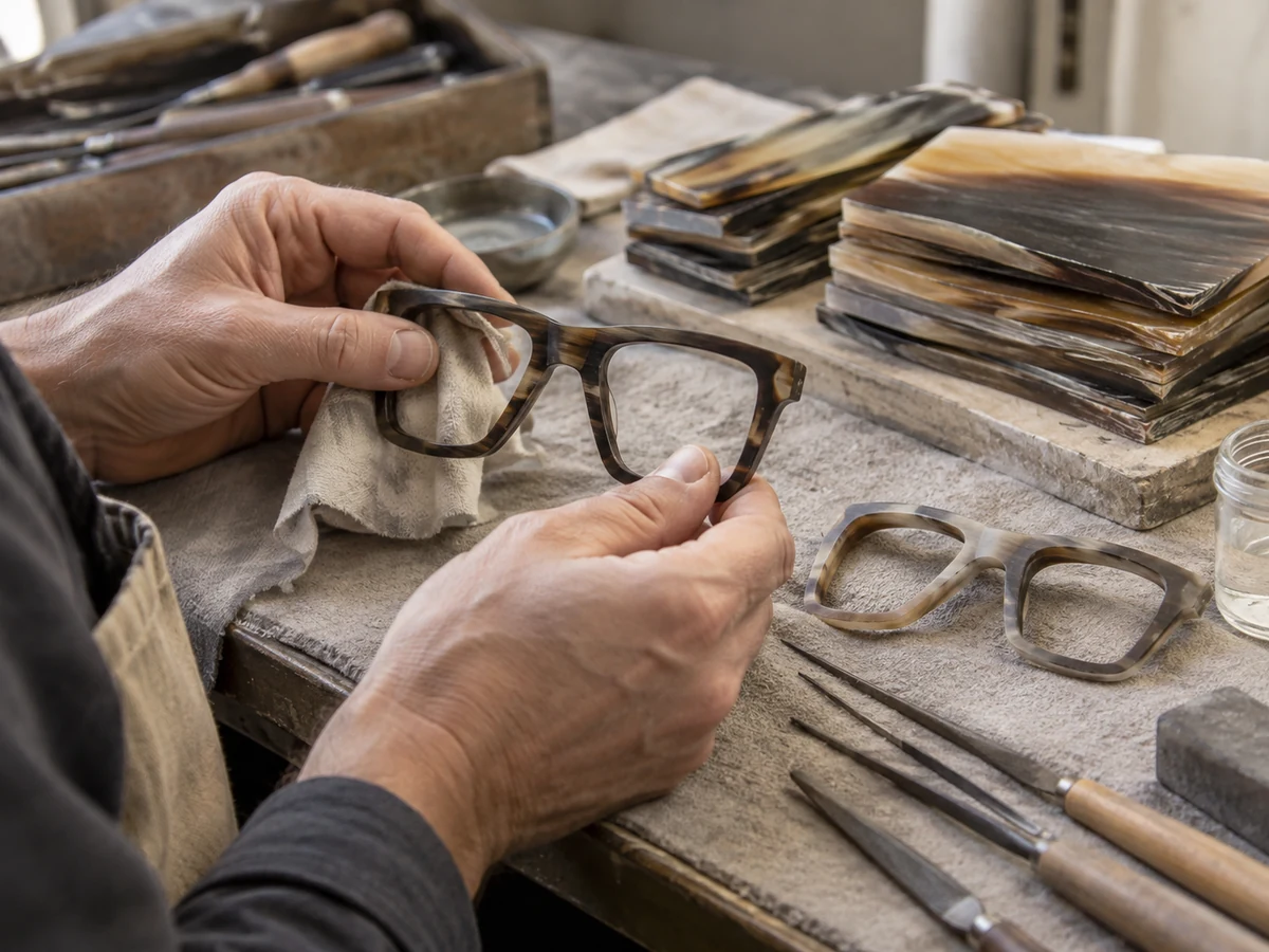
Step 03
Smooth & polish
Refine the contours and polish carefully to reveal the natural pattern.
-
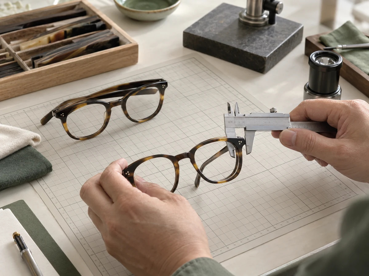
Step 04
Assemble & match
Fit components, check alignment and inspect the finished pair for material defects and colour balance.
What matters here
Natural grain, material condition and gentle finishing; each pair will look slightly different.
Production route 09
3D-printed nylon
Built in powder, then finished by hand.
This example follows a powder-bed nylon route. The geometry is created digitally rather than cut from a sheet or formed in an injection mould.
-

Step 01
Prepare the build
Check the CAD geometry, fit allowances and part orientation, then arrange the parts for printing.
-
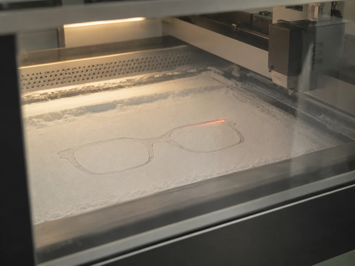
Step 02
Print & cool
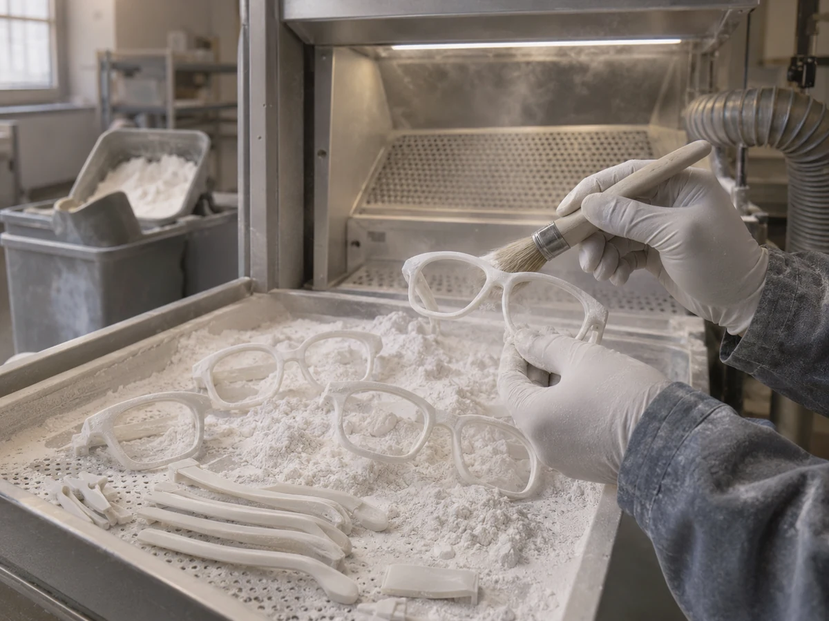
Build the nylon parts in the powder bed, then allow the build to cool before recovery.
-
Step 03
Clean & finish
Remove loose powder, refine the surface and apply the approved dye or coating.
-

Step 04
Assemble & verify
Fit hinges and lenses; check surface consistency, dimensions and component fit.
What matters here
Build orientation, powder removal and finishing allowances around the lens groove and hinge seats.
Production route 10
Combination frames
Separate material routes, one precise assembly.
Acetate and metal components are made and finished through their own routes before they come together in the final frame.
-

Step 01
Define the interfaces
Approve how the front, bridge and temples connect, including fasteners and fit tolerances.
-
Step 02
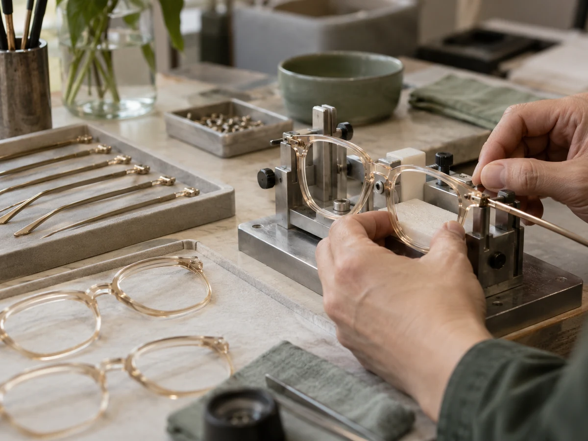
Make each component
Machine and finish the acetate parts; form, join and finish the metal parts separately.
-
Step 03
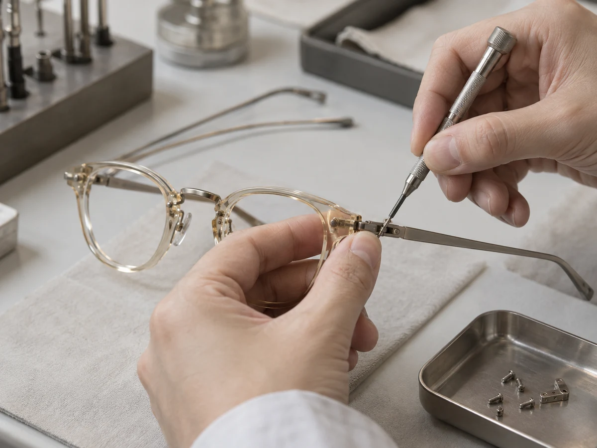
Bring them together
Assemble the components in alignment fixtures, protecting the finished surfaces.
-

Step 04
Check the whole frame
Inspect joint security, material transitions, symmetry and lens seating against the sample.
What matters here
Interface tolerances, secure joints and compatible finishing across both materials.
Facts you can check
- Capacity
- [Frames per month, by material]
- Team
- [Number of designers, developers and QC staff]
- Quality control
- Incoming material checks, in-line checks after each process, and a full pre-shipment inspection against your approved sample. You receive and approve the report.
- Certifications
- [Only certificates you hold, e.g. ISO 9001, CE, FDA registration]
- Markets
- [Countries you already ship to]
- Visits
- Brands are welcome to visit the studio and workshop. Ask your project manager to arrange it.
Tell us about the collection you have in mind.
Five short steps, about ten minutes. Not sure about something? Choose “Not sure yet” and we will help.